User Manual
T7H Sender
User Manual
Version: V1.0 |
2015/11/26 |
User Manual
T7H Sender
User Manual
Version: V1.0 |
2015/11/26 |

User Manual
Version: V1.0 |
2015/11/26 |

User Manual
I.Product introduction
T7H sender is the most commonly used synchronous system sender, it is
adopted the
easy cascading between sender cards.
It supports wide working voltage with AC 100~240V and has good stability and compatibility with all Colorlight’s control cards.
Version: V1.0 |
2015/11/26 |

User Manual
II.Hardware
2.1Front panel
2.2 Interface functions
|
NO. |
Interface |
functions |
|
Noted |
|
|
|
|
|
|
|
1 |
Power switch |
Power on /off |
|
|
|
|
|
|
|
|
|
2 |
Power supply |
AC power supply interface |
|
|
|
|
|
|||
|
|
|
|
|
|
|
|
|
|
|
|
|
3 |
Cascade output |
For output cascade signal to the next T7H |
|
|
|
|
|
|
|
|
|
4 |
Cascade input |
For input cascade signal from the last T7H |
|
|
|
|
|
|
|
|
|
5 |
Indicator lamp |
Indicate sender working state |
|
Red for power, |
|
|
green for signal |
|||
|
|
|
|
|
|
|
|
|
|
|
|
|
6 |
Output port A |
RJ45, connect to the receiver card |
|
The control |
|
|
|
|||
|
|
|
|
|
area of port A |
|
7 |
Output port B |
RJ45, connect to the receiver card |
|
|
|
|
and B can be |
|||
|
|
|
|
|
|
|
|
|
|
|
|
Version: V1.0 |
2015/11/26 |
||||

User Manual
separately set
8 |
|
Multifunction |
|
Audio input |
transmit the audio signal to the multifunction card |
||
|
|
card needed |
|
|
|
|
|
9 |
USB |
For T7H and PC communication |
|
|
|
|
|
10 |
DVI |
DVI signal input |
|
|
|
|
|
11 |
Digital tube |
Show the brightness adjustment levels of the |
|
sender |
|||
|
|
||
|
|
|
|
12 |
Selection bottom |
Used for brightness adjustment |
|
and assisted selection |
|||
|
|
Version: V1.0 |
2015/11/26 |

User Manual
Hardware Connection Diagram
T7H hardware connection diagram is as below:
Illustrate
1Support AC
2HDMI/DVI connection:
T7H has HDMI and DVI two video input interface, choose any one of them to
input video according actual. If you need to switch video input mode between HDMI and DVI signal, can use HDMI and DVI cable to connect the computer and T7H at the same time.
3 Control signal connect
Connecting the computer and the T7H with
4Ethernet Cable
Connect receiver cards and T7H by using Ethernet cable (Note: The Ethernet
cable must be CAT5E or CAT6)
Version: V1.0 |
2015/11/26 |

User Manual
III.Operating Environment
4.1Computer configurations
CPU Frequency >= 2.0GHZ
Host Memory >= 1G
Graphic card with DVI interface: Memory ≥512MB
Computer configuration can be adjusted according to the actual situation. Adjustment mainly aims at total pixels of LED display, complex playing program and whether playing HD video or not. Please note that the PC’s graphic resolution should be equal to or more than LED display’s.
4.2USB driver installation
There are two methods for installation USB driver.
1、Check ‘USB Drive For Sending Card’ when install the LEDVISION, as you can see in following picture.
2、Open the
Version: V1.0 |
2015/11/26 |
User Manual
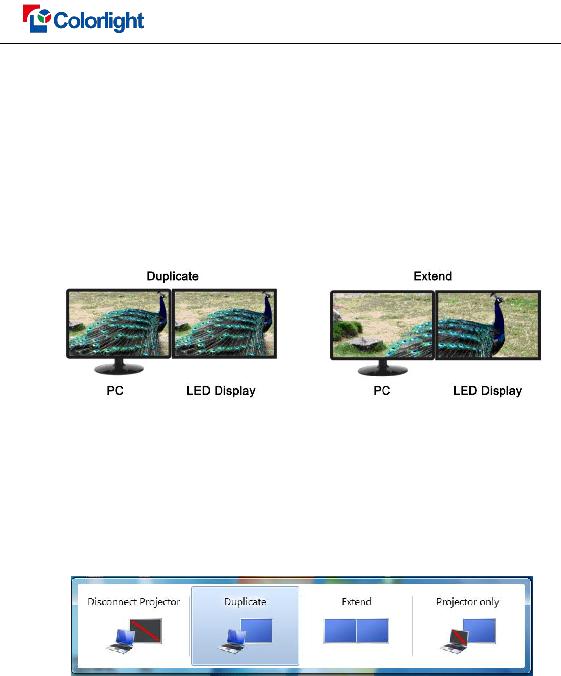
4.3Graphics Card Settings
Select duplicate or extend in graphics card mode, and their difference is that led display show the contents consistent with computer in duplicate mode, while in extend mode show only the window you want to display. (As shown in
How to change the mode, there have different ways in different computer. For example, WIN 7/8 system and NVIDIA graphics cards, please read the following settings ways.
The first way: Hold down the WIN and P keys at once, and select the mode as you want in the
The second way:
Version: V1.0 |
2015/11/26 |

User Manual
Version: V1.0 |
2015/11/26 |

User Manual
IV. Parameter Configuration
First of all, please make sure the software in i Series Mode before setting.
Click the “Setting” > “Software Setting” to enter the Software Management window
(Shown as
4.1 Hardware Connection Check
Please make sure the hardware connection correct and software is in i Series Mode before setting.
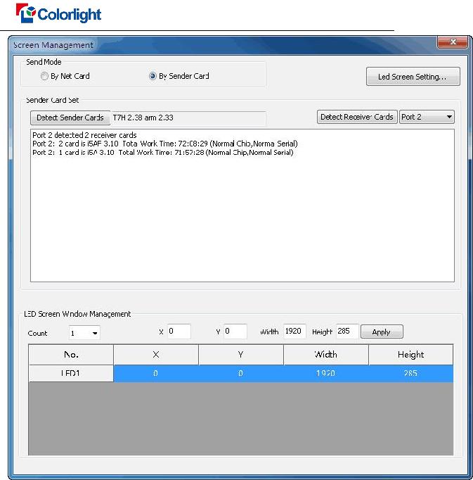
5.1.1 Detect Sender Cards
Run software, click the “Control” > “Screen Management” to enter the Screen Management window, the Sender Mode select “By Sender Card”, Click “Detect Sender Cards”, the sender cards information will show in the interface, (as shown in
Please check the hardware connection if cannot detect sende
Version: V1.0 |
2015/11/26 |
User Manual
5.1.2 Detect Receiver Cards
Select network port and click “Detect Receiver Cards”, the software will automatic acquisition the Receiver (Receiving card) quantity for each network port of the sending card. Please check cable if the numbers of receiving card are inconsistent with actual. (As shown in
Version: V1.0 |
2015/11/26 |
User Manual
5.2 LED Screen Setting
Click “Led Screen Setting” by using password: 168 to enter the Led Play Screen Setting interface, click “Advance Settings” (As shown in
5.2.1 Sender Card Setting
Version: V1.0 |
2015/11/26 |
User Manual
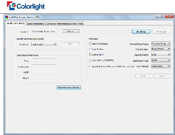
Sender Card Resolution: In general, it should be consistent with graphics cards
Input Signal Information: Software will automatically collect parameter from the sender card.
Advanced Settings: This feature is only for professional and technical personnel to set up special applications, nonprofessional personnel are not allowed to operate. It contains the following parameters setting in Advanced Settings.
3D Setting: T7H is no need to set this item because only for 3D Sender feature setting.
Write Logo: Can be written to the customer specified image such as logo, and display before the video signal is not input.
Zero Frame Delay: Enabled by the professional and technical personnel or it will display abnormally.
Auto Switch (DVI, HDMI): The transmitter only identifies the set of video signals when selected; the signal of the first access can be automatically identified when not checked.
Adjust Brightness Based on
Network Date Types: The software default is “Standard Frame”; please
Version: V1.0 |
2015/11/26 |

User Manual
consult professional and technical personnel if you want changing.
Frame Output: The software default is “Every Frame”; please consult professional and technical personnel if you want changing.
Input Bit Depth: The software default is “8bit”
Signal Input Type: Select HDMI or DVI according to the interface of
video source devices
Sync Method: The software default is “Auto Select”
5.2.2Screen Parameters
Observe the display screen with single cabinet as unit, if all cabinets display normally (the picture between cabinets is not continuous but also as normal), please ignore this step directly into next step.
Otherwise, enter the following configuration:
The first step: Click “Load” to select the correct parameter file for your LED display
The second step: Click “Send” to send the parameter to receiver cards, at this moment, all cabinets should display normally (the picture between cabinets is not continuous but also as normal), then click “Save To Receiver”.
Please contact display manufacturer of engineering and technical personnel if display abnormally.
Version: V1.0 |
2015/11/26 |

User Manual
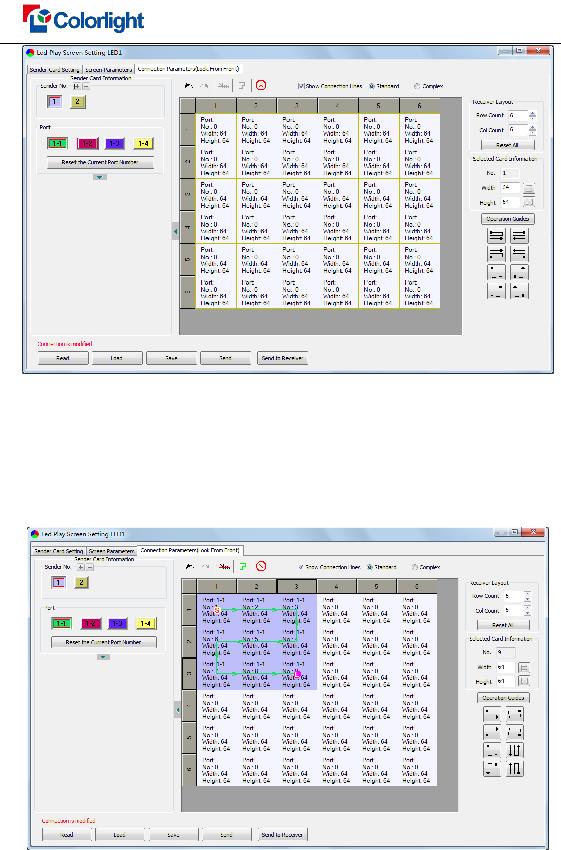
5.2.3 Connection Parameters (Look From Front)
In i Series Mode, LED screen just needs set up the Receiver (Receiving card) connection relationship for each network port of the sending card, the software will automatically calculate the network port control area. Specific setting as following:
1)Receiver Lay out Setting
Set how many Receiver (Receiving card) are used in Row Count and Col Count (6*6 as an example), how many pixels one Receiver (Receiving card) manages in Width and Height (64*64 as an example), in the software interface right you will see led display mapping area (Viewing from the front of led display). (As shown in Fig.
Fig.
2)Receiver Card Parameters Setting
Select corresponding “Sender No.” and “Port”, when conduct Receiver (Receiving card) connection. Configuration Receiver (Receiving Card) connection pattern for each port individually if more than one port are used. There are two methods to set up.
Note: Set up connection Receiver (Receiving Card) must be based on fact.
Version: V1.0 |
2015/11/26 |
User Manual
Using Mouse Select One By One
Based on the actual connection of the Ethernet cable, click the Receiver (Receiving card) one by one until the last one of this port load, connection lines will show in the display mapping area (Viewing from the front of led display). As shown in
Connection Pattern
Select the connection pattern based on fact, and then select this port load Receiver (Receiving card) in the display mapping area. (As shown in
Version: V1.0 |
2015/11/26 |

User Manual
If some Receiver (Receiving card) manage different quantity of pixels from others, specific Receiver (Receiving card) Size in Width and Height can be set individually. (As shown in
3)Send to Receiver
After set up the Receiver (Receiving card) parameters and connection pattern for each network port of the sending card, LED display will available when click “Send”.
Please determine that no mistake then click “Send to Receiver” to save the parameter
Version: V1.0 |
2015/11/26 |

User Manual
in Receiver (Receiving card).
Version: V1.0 |
2015/11/26 |