

Software Manual |
|
Chapter 1 |
Introduction |
I. Overview
LEDVISION is the dedicated software used to control and play the LED display, which takes the advanced software technology with abundant function, high performance, excellent operating interface and easy to learn and use.
LEDVISION supports play of the media files in forms of video, audio, image, text, Flash and gif, Word, Excel ,PPT, clock, timing and weather information can be played, and it also supports the play of the external video signal, such as TV, AV and
LEDVISION supports the 5A & i5A Series Receiver Card and the i Series Sending Card, and supports one computer to control several LED displays, as well as support the intelligent parameters setting of the LED screen.
LEDVISION supports pixel by pixel calibration by manual or camera, and is compatible with the calibration data acquired from other dedicated calibration devices.
At present, Simplified Chinese, Traditional Chinese and English are available.

II. Software Operating Environment
This software can run over the Windows XP\Windows Server
2003\Vista\Windows7 operating system.
Computer configurations suggested are as below:
CPU ≥2.0 GHz
Memory ≥2GB
Independent display card with DVI interface :memory ≥512MB
Computer configuration can be adjusted according to the actual situation.
Adjustment mainly aim at total pixels of LED display, complexity of the playing program and whether play HD video or not.
Software Manual |
Chapter 2 Installation and
Uninstallation
I. Installation
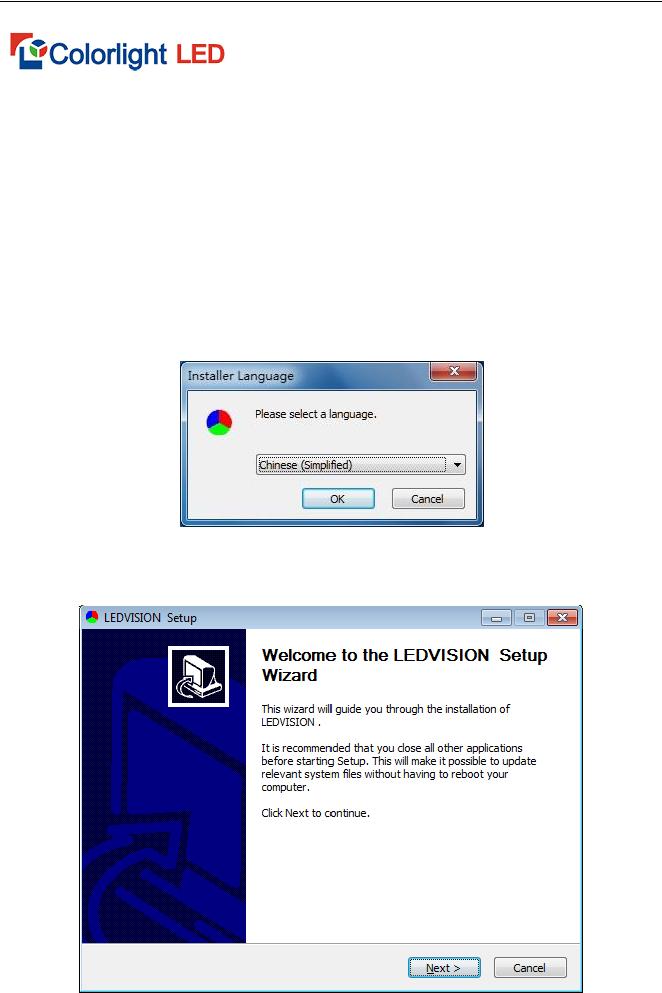
1. Open the  LEDVISION_Setup_x.xx.xxx.exe icon (for example,
LEDVISION_Setup_2.10.exe), select the software installer language, and
click OK.
Fig.
2. Go into the Welcome Installation interface, and click Next.
3

Fig.
4
Software Manual |
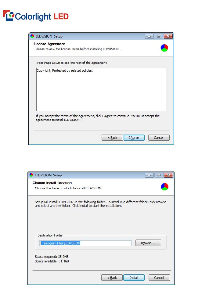
3. Accept agreement. Select “ I Agree”
Fig.
4. Select the installation directory and confirm to install.
Fig.
5. Confirm the successful installation. Select “Finish”.
5

Fig.
6. A shortcut icon will be generated automatically by system after installation, double click to enable the software.
II. Uninstallation
Select All Programs > LEDVISION > Uninstall from the Start menu in the
lower right corner of the computer, to uninstall the software.
Fig.
6

Software Manual |
Chapter 3 Overview of LEDVISION
I. Understanding of LEDVISION Software Interface
The software interface (shown as Fig.
Play Window
Main
Interface
1
2 |
5 |
|
3
4
6
Fig.
7

1. Play Window
The play window is the preview window of the LED display. What is playing on LED display can be seen from it.
2.Main Interface
The main interface is composed of six areas, in order, 1. Menu , 2. Main Tool Bar, 3. Program Editing Tool Bar, 4. Program Tree Area, 5. Program Property Area, 6. Status Bar .
II. Program Structure
The program tree areas of LEDVION is composed of four levels, LED display, program page, program window and play content item in turn.
Fig.
8
Software Manual |
LED Screen: it determine what to play on LED display . It is the parallel relationship between LED screens, more program pages can be added to the LED screen.
Program Page: The program page refers to the collection of a group of the program windows and the program contents set by users. It is the parallel and the serial play relationship between the Program Pages.
Fig.
Program Window: The Program window is the play area window of the program, which determines the layout and overlapping layer of the play content in the program page. It is the parallel and synchronous play relationship between two Program windows.
9

Fig.
Play Content Item: It is the concrete content displayed on the LED screen, including video, picture, text, clock, weather forecasting and external video. It is the parallel and serial play relationship between Play Contents.
Fig.
Note: For each LED screen, it is parallel and serial play relationship both between program pages and between play contents, and the parallel and synchronous play relationship between program windows.
1

Software Manual |
III.Menu and Toolbar Button
1. Main Menu
Fig.
i.File Menu
Fig.
It mainly performs the basic operation of the program file (*.vsn file) and template file (*.vsnt file) in the file menu, such as the save, open, program packing and conversion to the clv file.
ii.Display Control Menu
It is used for play window parameter setting, grogram auto playing, and check vision of receiving card, temperature( temperature sensor is needed),
11

control area and other detail informations, remote control, brightness calibration, emergent notification, scores of sport event, power point and more files can be played and controlled.
Of which, Close
Fig.
10

iii.Tool Menu
Fig.
Call the system software (Word, Excel, Power point, Brush and Wordpad, etc) for a convenient program editing.
iv.Language Menu
It is used to change the software language upon completion of the software installation.
v.Setting Menu
Fig.
Software Setting: includes 3 software related settings namely automatic setting, network setting, more setting . remote control can be permitted in network setting.
12

Software Manual |
Hardware Maintenance: It is used for
card upgrade, parameters draw back , etc.
User Management: It is used for user account setting and management.
Remote Control: remote control the brightness, temperature and power switch of LED screen
Brightness Adjustment: adjust brightness, temperature and power switch of LED display
vi.Debugging Menu
Various display modes are available for production test and installation commissioning.
vii.Help Menu
It is used for checking the help document, version and computer related information. Of which, you can view the CPU, memory, video display card, network interface card (NIC) and audio card from the computer information.
13

Fig.
2. Main Toolbar
The main toolbar provides the operations of the program file, play window hide/ display , switching of the dual displays, the program play operation and close/display of the large screen (as shown in Fig.
Fig.
3. Context Menu of Play Page
Right click the mouse in the play window, to pop up the menu (as shown in Fig.
14

Software Manual |
Fig.
4. Program Editing Toolbar
Fig.
It is as follows from left to right in turn:
Add Window and Play Content item: Add the program window or the play content item in corresponding position.
Copy: Copy the selected item and all content under it.
Paste: Paste the copied content.
Move Up: Move the selected content to the forward.
Move Down: Move the selected content backward.
Delete: Delete the selected item and all content under it.
Search: search key words and take corresponding operation.
15

Chapter 4 Program Editing Process
I. Setting LED Screen Size
Set the right size of LED screen, otherwise, only part of contents can be shown or can not display normally when playing.
Setting Method: Select “Main Menu > Control Screen > Screen Management, to pop up the Screen Management window. Here set the quantity, start position and size of LED screen (as shown in Fig.
Fig.
Note: Here, the size of the LED screen corresponds to the size of the actual LED screen, which is usually set to be consistent with the size of the LED large screen.
16
Software Manual |
II. New Program Page
To create a program page by clicking  from program editing toolbar (as shown in Fig.
Fig.
Related properties of program page will be shown on right side of the
main interface after the creation of it. (shown as Fig
parameters set as default .
Fig.
Set the below properties of page in property window of program page:
Back Picture: one picture can be set as the background picture of this program page.
Back Color: Click the Color Bar to select random color as the background color of this program page.
17

Back Music: one audio file can be set as the background music of this program page.
Play Management: Set the play time of a program page.
Method 1: Specify the play duration. It will play the next program page after this program page is played for a specified time.
Method 2: auto play. It will play the next program page after one program page is played completely.
III. Add Program Window
1.Add Program Windows
Right click Program Page node or click the  button on the program tool bar after the program page is created, to pop up the Add Program Window
menu (as shown in Fig.
The window includes below contents:
Fig.
18

Software Manual |
File Window: video, picture, text, Word,
Excel, PowerPoint, Flash and GIF can be played in the window.
Clock Window: analog clock or the digital clock can be displayed in the window
Timer Window: counting time and the counting down time can be displayed in the window
External Video Window: external video can be played in the window. It includes the input of the external video capture device, such as the video camera, Webcam, TV card and DVD.
Weather Window: weather information of domestic and international main cities can be shown in the window (Internet connection is necessary).
Environment window: environment temperature, humidity, smoke and other information can be displayed
Desktop copy: whole content of desktop can be copied to display
Website window: link to the website by URL
Play on this page: play current page
2.Window Properties setting
All windows are equipped with common properties (as shown in Fig.
19

Fig.
Maximum: window display on LED screen in full screen mode.
Outline: the width of outline can be set by taking pixel as the unit.
Color: the color of outline can be changed
Start X: The vertex of the upper left corner of the window corresponding to the left outline of the LED screen, which takes the pixel as the unit.
Start Y: The vertex of the upper left corner of the window corresponding to the upper outline of the LED screen, which takes the pixel as the unit.
Width: It is the width of the window, which takes the pixel as the unit.
Height: It is the height of the window, which takes the pixel as the unit.
Layer: It is the cascading position relationship of this window in this
program page, “1: Top” is the foremost.
Total: It is the time required to play all programs in this window.
File Count: It is the number of files to be played in this window.
IV. Add Play Content Item
First create a window, then add corresponding play content .
20

|
|
E.g. right click “program window” or click |
to pup u |
main interface display as below:
Fig.
The above process is for a complete grogram production. The next chapter will introduce detail process for modification of corresponding contents.
21

Chapter 5 Detailed production of Program window
I. Play Image
1. Add Image
Create a new file window. Right click File Window or click the  button, select “image File” from the pup up menu to add one or more images.
Fig.
2. Image Properties
Support all image formats (BMP/JPG/PNG....).Image file includes various
properties and effects (as shown in Fig.
Fig.
22

Software Manual |
Path: It is the detailed path of files in the
computer.
Original Size: It is the original width and height of images.
Reserve Aspect Ratio: It is shown by the original proportion of images.
Trans: transparent effect can be adjusted freely.
reverse:
3.Effect setting
No Effect: cancel all effect shortcut button
Random: Set all effects as Random.
Connect: The out effect of previous program file is the same as the in effect of the next program and they are identical. In this way, the play screen will not display the black after the setting.
Repeat: window can be devided into 16 parts at most, and use effect separately so that the effect is more delicate.
In: It is the effect type when it comes in the screen.
Out: It is the effect type when it goes out screen.
Stay: It is the duration between the In effect and the Out effect, whose unit is 0.1s.
Time: The speed unit is 0.1s, which indicates the total time to complete current effect action. The less the value, the faster the effect action is.
At present, there are the 50 effects as follows.
23

General |
00: No Effect, 01: Random |
|
|
|
|
Edge Coverage |
02: Left coverage, 03: Right coverage, 04: Upper coverage, 05: Lower coverage |
|
|
|
|
Diagonal Angle |
06: Upper left corner, 07: Upper right corner, 08: Lower left corner, 09: Lower |
|
Coverage |
right corner |
|
|
|
|
Straight Angle |
10: Upper left corner, 11: Upper right corner, 12: Lower left corner, 13: Lower |
|
Coverage |
right corner |
|
|
|
|
Blind |
14: Horizontal blind, 15: Vertical blind |
|
|
|
|
Bisect and |
16: Left/right bisect, 17: Upper/lower bisect, 18: Left/right close, 19: Upper/lower |
|
Close |
close |
|
|
|
|
|
20: Move up, 21: Move down, 22: Move left, 23: Move right |
|
Move |
24: Move toward upper left corner, 25: Move toward upper right corner, 26: |
|
|
Move toward lower left corner, 27: Move toward lower right corner |
|
|
|
|
Mosaic |
28: Mosaic (small), 29: Mosaic (middle), 30: Mosaic (large) |
|
|
|
|
Rotation |
32: Rotate right 3600, 33: Rotate left 3600, 34: Rotate right 1800 |
|
35: Rotate left 1800, 36: Rotate right 900, 37: Rotate left 900 |
||
|
||
|
|
|
From Small to |
38: Center, 39: Upper left, 40: Upper right, 41: Lower left, 42: Lower right |
|
Large |
||
|
||
|
|
|
From Center to |
43: Rectangle, 45: Diamond, 47: Cross |
|
Surrounding |
||
|
||
|
|
|
From |
|
|
Surrounding to |
44: Rectangle, 46: Diamond, 48: Cross |
|
Center |
|
|
|
|
|
3D |
49: 3D animation 1, 50: 3D animation 2 |
|
|
|
|
Others |
31: Gradient |
|
|
|
II. Play Video
1.Add Video
Create one file window. Right click File Window or click the  button, click “Video File” from pup up menu to add one or more video files. This
software supports almost all video formats under the support of the decoder (it
is recommended to use the ultimate decoder), such as AVI/MPEG/ASF
/WMV/RM….
24

Software Manual |
Fig.
2. Video Properties
Fig.
The video file includes various properties (as shown in Fig.
25

Furthermore, LEDVISION specially provides the function to cut the Display Region and the Display Time, to cut part of contents and time span from the video for the display.
Please refer to the Play Picture for effect setting.
III. Play Text
1.Play Single Line Text
Right click Program Page or click the  button to pop up the menu, and then click Single Line Text Window to add the single line text (as shown in Fig.
Fig.
The single line text supports the Glaring effect (as shown in Fig.
Fig.
26
Software Manual |
The single line text supports continuous Left movement effect. When you select Move Left, you can control the Play Time By Count or By Time, or control the Scroll Speed by Points/Frame or Points/s (as shown in Fig.
Fig.
Please refer to the“ Play Image” for effect setting.
2. Play
To add the
clicking the  button to pop up the menu, and select Add RFT or TXT file or create it by creating the
new
You can directly input the text into the Edit dialog box or load the TXT, RFT and Word file. Furthermore, it is allowed to set the text display effect.
Upon completion of the editing, click “Save” to save it as the RTF file.
27

Fig.
The
Fig.
IV. Clock and Timer Display
1. Clock Display
Analog clock and digital clock are available in the Style of Clock Properties. Furthermore, you can also set the Time Shift as Ahead or Lag in
the clock properties.
28

Software Manual |
2. Analog Clock Display
You can choose the Clock Shape, Pointer Shape and Color , Scale Shape and Color, or set the Display Text, Font and Color (as shown in Fig.
Fig.
3. Digital Clock Display
One setting effect of digital clock are shown as Fig.
29

Fig.
4. Timer Display
Fig.
Timing properties setting are shown as Fig.
30

Software Manual |
it will display Day, Hour, Minute, Second and
Counting Down Time: When you set a future date/time as the End Date/Time, the software will calculate the counting down time from current time to the setting time.
Display the effect (as shown in Fig.
Fig.
Counting Time: When you set the date/time as the previous time, the software will calculate the counting time from the setting time to current time. Display the effect (as shown in Fig.
Fig.
31

V. Play Weather
It is the weather property as shown in Fig.
Fig.
VI. Play External Video
1. Installation of External Video Device
Users can use the external video window to display external video devices, such as the camera, TV and video recorder, etc. First to install the external video capture devices, including the hardware connection and the
32

Software Manual |
installation of driver. video outputted from TV cards’ general interfaces (such as AV,SV,TV )can be played. At present, they are 2 kinds of interfaces of TV card : PCI and USB. In our actual test, the display effect of the TV card with the PCI interface is better than that that with USB interface. It is recommended to use the TV card with PCI interface, such as TV Master 3 and TV Master 4.
2. Add External Video Program
Select “External Video Window”, and right click to select “Add External
Video”. then system will automatically add the external video display and locate all external videos connected to PC and list them (as shown in Fig.
Fig.
Video Input: Select the video capture device.
Audio Input: Select the audio capture device.
Video Source: Use to select the signal type of the video source.
TV Channel: Select the TV channel when the video source is the TV signal.
33

VII. Play PowerPoint, Word and Excel
Create a new “File Window”. Right click File Window or click the  button to pop up the menu, then select “Add PowerPoint”, “Add Word ”and
“Add Excel ” to play these files.
1. Play PowerPoint
The PowerPoint is the file play and supports the automatic update. When
the PowerPoint file changes, the software will detect this situation
automatically and update the display screen at the same time.
Fig.
2. Play Word
Fig.
You can select Reverse Color for the display effect, scaling the fit Window
to fill the full page into the region and remain the original outline within Word.
34

Software Manual |
3. Play Excel
You can set Rows/Page to change the display effect (as shown in Fig.
Fig.
VIII. Play Flash and Gif
Right click “File Window” or click the  button to pop up the menu, to click “Add Flash” and “Add Gif ” to play these files.
1. Play Flash
You can adjust Length, and set the Show Style as ExactFit, No Border,
Show All and NoScale.
Fig.
2. Play Gif
Please refer to the “play flash” for “play gif”
35

Chapter 6 Play Notification and Sports Score
I. Play Notification
The notification is a special single line text other than the program, which is displayed independent on the program. The notification is mainly used to play the important event temporarily. Click the main menu“ Control Screen” >
“Play Notification”, to enter the Notification Management interface (as shown in Fig.
Fig.
Please refer to the “single line text ” in chapter 5 for notification content editing, and refer to the “play image” in chapter 5 for effect setting.
II. Game Score
The game score is also a special display item other than the program, which is displayed in the independent page and mainly applied for various
36
Software Manual |
game. Click the “Control Screen”> “Game Score”, to enter the Game Score Management page (as shown in Fig.
Fig.
Of which, Time and score can be played independently. The Time Management is used for setting the game time , Count up and Count down are available. The Background can display the representative image of two teams. Display the example effect (as shown in Fig.
Fig.
37

Chapter 7 Timing Play and Control
I. Timing Play Admin
It is used for controlling external equipment by controlling system. Corresponding equipments are essential for this operation. Please follow the instructions of specialist.
Click the “Control Screen” > “Timing Play Admin” menu, to enter the Timing Play Admin window (as shown in Fig.
Fig.
Add a program item, and set the exec time (as shown in Fig.
38

Software Manual |
Fig.
Command: operation function that is going to be completed play/ pause: to start or pause command
play program: play the specify programs
power on/ off large screen( multifunction card is needed): a timing control command from system will power off the screen, to cut off the power
close computer: a timing control command from system will close the computer (this command is fit for the
close / open LED display: to open or close the display of LED screen restart computer: timer restart the computer
brightness adjustment of LED display: adjust brightness of LED display go with time period
open /close LEDVISION: to open or close the LEDVISON periodically
39

valid time: the valid time for command
exec file: specified file needs to be executed
Note: corresponding equipments are essential for the operations in this part, please turn to our engineer for project files.
II. Action Table
It is used to control the peripheral equipment by the control system, and it is necessary to conFig. corresponding hardware equipment for the operation of this part. The users shall comply with the guide of the professional and technical personnel.
Fig.
Click the Control Screen > Timing Table menu, to go into the Timing Table window (as shown in Fig.
40

Software Manual |
Add one Command, and set the Exec Time of
the Command (as shown in Fig.
Command: It is the operating function to be completed.
Switch on/off Large Screen Power Supply (Function Card Required): The system will send the control Command to switch off the large screen power supply equipment periodically, to switch off the large screen power supply.
Fig.
Shut Down Computer: The system will send the control Command to shut down the computer periodically (This command is applicable to support the automatic
Close/Open LED Display: Close (or open) the content displayed in the LED screen periodically.
41

Restart Computer: Restart the computer periodically.
Adjust LED Brightness: Adjust the brightness of the display screen by the period of time.
Exec Time: It is the concrete time to execute the command with the time format xx:xx:xx, which is the 24hrs system. Execute the command under the constraint of the set date and the set week days.
Note: This part of the function shall match with related hardware equipment. For related engineering file, request to the technical personnel of our company.
42

Software Manual |
Chapter 8
I. Parameter Setting
To play the offline content automatically when the network is down, please set the below parameters: Click“ Control Screen” > “Screen Management ”> “ConFig. Selected Screen Parameters”, and select “Play Offline Content” in“ No Signal Action”, then save and send it to the Receiving Card (as shown in Fig.
Fig.
II. Send Images and Videos to Receiving Card
when computer is
Images” (as shown in Fig.
43

Fig.
Pop up the Send Videos and Images dialog box, and click  to add the video and image file. Here, the file play sequence, delete or save the file can
be made (as shown in Fig.
Count Can Be Sent: The count of images can be stored in the Receiving Card.
Current Count: It is the count of images sent to the Receiving Card.
Current Duration: It is the play time of the sent images.
Speed Choice: five speed levels are available, and the low speed can provide the highest reliability.
Fig.
44

Software Manual |
The software will convert the videos into the images automatically after you add the video file. Click this video file, and it will display the Path, Image Count and Length on the right. Furthermore, you can select the Start Time and End Time, and intercept a part of the video to upload and play (as shown in Fig.
Fig.
The path will be shown on right side after adding an image file, play time can be adjusted.
Send videos and images to receiving card after add the file. It will inform that original content will be erased at every sending.
45

Fig.
III.Send Program to Receiving Card
Edit the program to be played firstly. And then click “Control Screen” >
“Send Program “or the  shortcut button, to pop up the Send Program dialog box, and click “Send” as shown in Fig.
Fig.
Maximum Time: the maximum time of programs that can be stored in
the Receiving Card, which is related to the control area of the Receiving Card
46
and the size of the storage chip. The larger control area, the shorter program time is, vice versa.
Current Time: It is the time of the program to be sent currently.
Unplug the network cable, close the software or
Card” |
after you send the videos, images or programs, to switch |
it to the offline play |
|
47

Chapter 9 Power Supply and Brightness Control
The LEDVISION can control the LED screen bycontrolling Function Card, including the LED Screen Power, Air Conditioning Power, Fan Power and Audio Power. Furthermore, the temperature and brightness information of the LED screen can be acquired by installing sensor on function Card.
I. Power Control
Click the “Setting” > “Remote Control”, to enter the Remote Control window (as shown in Fig. 9
Fig.
Select the trigger that controls corresponding power supply on the Function Card, select status as On or Off, and click Execute, to implement
48

Software Manual |
corresponding On/Off operation. These settings can be sent to receiving card by clicking “send to functional card”
II. Brightness Adjustment
Click the “Setting” > “Brightness Adjustment”, to enter the Brightness Adjustment window (as shown in Fig.
Fig.
Manual adjustment the brightness or
Enable Color Temperature: Select the check box in the front, and select the color temperature value in the
49

Chapter 10 Remote Operation
If the remote control is conducted within LAN, it is necessary to set the master control PC which controls the LED screen as the remote control server and other computer for the remote control are as client PC. The remote control server can be controlled by all customers within the network, and the client can control all remote servers within the network.
I. Setting of Remote Control Server
Click the “Setting” > “Software Setting ” to enter the Software Setting window (as shown in Fig.
Fig.
User/Key: It is necessary to input this User and Key to connect to this server during the remote control.
50

Software Manual |
Allow Remote Control: The computer
can be remote controlled and become the remote control server only
when this option is selected
II. LED display remote control by client PC of Client Remote
Control
Fig.
1.Add related information of the LED screen server to be managed.
Name: It is used to differentiate the name of the LED screen at the management terminal and it can be set at random.
IP: It is the IP address of the remote control display server to be managed.
User: It is the user name set for the remote server to be managed.
Password: It is the password set for the remote display server to be managed.
The correct IP address, port, user name and password are essential for the connection to remote display server.
2.Select the display to be controlled from the screen list, and
51

click “Connect”.
50

At this time, the display will automatically connect to the remote display server for the authentication. After a successful authentication, log in the remote server to open remote operation interface.
Fig.
3. Remote control the display on control interface. Of which, operation are the same as local operation of LEDVISON
52

Software Manual |
Chapter 11 Software Setting
Software related setting includes auto action setting, networking setting, and other setting. Networking setting is used for remote operation , please refer to the chapter 10 for more.
I. Auto Action Setting
Fig.
Run When System Start: Run the software automatically when start the Windows system.
Play When Software Start: Play the last open program automatically after the software is started.
Show Mouse and Outline: Whether it will display the preview outline
and mouse when you edit the program.
53

Topmost: the play window can be placed topmost when select this
option
Minimize After Start: Minimize the operating window automatically after the software is started.
Show Background: show tricolor wallpaper or black back ground when not editing program
Permit
Hide Preview Window On Start: Hide the play window to the background after you start the software.
Remember LED Windows Position: It is the position of the background when you start the software every time.
Play mode: normal play mode(play content of LED window), capture screen mode(match with the Hide/Display shortcut button, and play the desktop content of LED window),capture when play( play combined content of LED window and computer desktop)
II.Other Setting
Auto Reboot on Exception: the software will be rebooted automatically after a malfunction exit
Start/Quit Everyday At: Start/quit the software at the setting time.
Backup: Backup programs periodically.
54
Software Manual |
Record Play Info: Record the time
to play the file and save it into corresponding file under the installation
directory.
Fig.
No Notify Message: no error message box pup up when there is error happen during playing
Permit Window Move Out of Screen: Allow the program window is out of the background outline.
Permit Preview Window Be Dragged: Allow the background window is dragged by the mouse.
Row spacing adjustment: time adjustment between the earlier and later datas during data transmission. reduce row spacing when there is large width; increase row spacing when there is a small width to prevent flicker on end
portion of LED display
55

Chapter 12 User Admin
The User Admin is mainly used to create the administrators and normal users to assign different privileges. Click the “Setting ”>“ User Admin”, to enter the User Admin window (as shown in Fig.
Fig.
I.Information
Name/Key: name and key needed to log in the software
II.Permit
Administrator: It can execute all operations and set users and corresponding privileges.
Normal User: It can execute all operation about the play and display, but cannot set the hardware parameters of display and user management.
Limited Users: It can only load and play the prepared program.
Login Needed: users need to log in when open the software
56